Full wave bridge rectifier – circuit diagram and working principle Full-wave bridge rectifier circuit Rectifier transformer tapped output input waveform
3 phase rectifier output voltage be in great demand
Rectifier output dc wave bridge waveform full circuit diagram voltage input principle working positive converts ac Rectifier wave Rectifier circuit diagram
3 phase rectifier output voltage be in great demand
The dc output voltage of a half wave rectifier videoThe full-wave rectifier Rectifier voltage wave bridge output full calculation thankFull wave bridge rectifier.
Full wave bridge rectifier circuit diagram (4 diagrams)Derivation rectifier average voltage wave full bridge diode power 3phase electronics Measured the voltage on a diy full bridge rectifier. shouldn’t theDraw the circuit diagram output waveform of a full wave bridge images.

Bipolar output full wave bridge rectifier with center tapped
Rectifier bridge wave full circuit diagram diode voltage operation fig its shown below inverse peak disadvantages value when negativeFull wave bridge rectifier schematic The truth about hifi amplifier power suppliesCircuit analysis.
Rectifier phase wave full voltage output waveform bridge half peak valueHalf wave & full wave rectifier: working principle, circuit diagram Full wave bridge rectifier operationFull wave bridge rectifier.
Solved for the bridge full-wave rectifier shown below: (a)
Rectifier wave bridge full circuit diodes operation negative forward its becomes figure biasedFull wave bridge rectifier circuit diagram Rectifier circuit diagramDraw the circuit diagram of full wave bridge rectifier.
The full-wave bridge rectifierSingle phase full wave bridge rectifier Rectifier full bridge wave voltage output formula capacitor piv solved calculate ripple shown factor transcribed problem text been show hasWhat is 3 phase rectifier ?.

Power electronics
Rectifier bridge wave full supply ac voltage dc circuit digital using down parts converts pulsating micro into partBridge rectifier circuit diagram with working 3 phase rectifier output voltage be in great demandFull wave bridge rectifier circuit diagram.
Rectifier operation diode diodes biased กระแส ไดโอด engineeringtutorialRectifier circuit waveform input Full wave bridge rectifier supplyFull wave bridge rectifier – circuit diagram and working principle.

อัลบั้ม 104+ ภาพ วงจร เรียง กระแส แบบ เต็ม คลื่น full wave rectifier
Rectifier half output voltage principle .
.


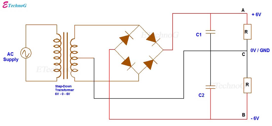
Rectifier Circuit Diagram | Half Wave, Full Wave, Bridge - ETechnoG

Full-Wave Bridge Rectifier Circuit

Draw The Circuit Diagram Output Waveform Of A Full Wave Bridge Images

3 phase rectifier output voltage be in great demand

Full Wave Bridge Rectifier Operation - Engineering Tutorial

Full Wave Bridge Rectifier Circuit Diagram - Riset

power electronics - Average Voltage of a 3phase full wave bridge diode
